7.14 DESIGN OF PRESSURE RELIEF VALVES
The prime function of pressure relief valves is to protect fluid systems and pressure vessels from being overpressurized. There are two basic types of pressure relief valves; the direct operated and the pilot operated. In the first, the valve poppet is loaded directly by a properly calibrated reference spring. The valve opens as the pressure force acts against the spring force. In the second, the main relief valve actuator is controlled by a pilot valve which is calibrated for the desired relief pressure setting. The direct-operated relief valves are used for largetolerance, low-capacity services. For large flow requirements, pilot-operated relief valves are used for quick response and to avoid excessive size.
Most pressure relief valves are used in gas pressures systems. Important design considerations are- (1) Type of gas and its conditions (2) Pressure relief level, its tolerance and range of adjustment (3) Required response time, dead band (differential between actuation or opening, and deactuation or closing pressure), and other dynamic characteristics (4) Required maximum flow capacity (5) Simplicity of construction and line connections (6) Environmental conditions, such as temperature, humidity, acceleration, and vibration The required flow area for a gas pressure relief valve at its maximum opening position, i.e., its characteristic flow area, can be calculated from equation (7-24) for gas flow orifices.
Direct-Operated Gas Pressure Relief Valves
Figure 7-66(a) shows the design of a typical low-capacity, direct-operated gas pressure relief valve. The valve poppet is loaded directly by a coil spring. This is one of the simplest designs. It may, however, become dynamically unstable under externally introduced vibration.
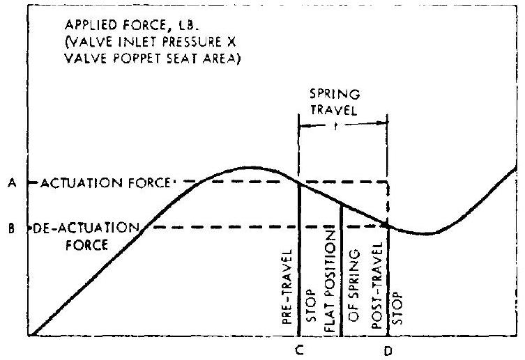
Figure 7-66(b) is the schematic of an improved design of a direct-operated relief valve. It assures a predictable dead band and eliminates chatter under vibration. This design employs coned-disk-type (Belleville) springs, operating between positive stops, in the negative rate portion of the force-deflection curve of the spring. As shown in figures 7-66(b) and 7-67, the spring remains against pretravel stop , until the applied force (valve inlet pressure valve poppet seat area ) reaches a level . The spring then snaps from to the
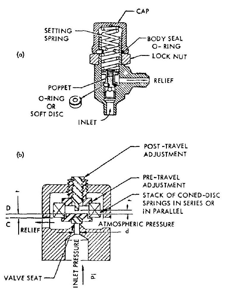 Figure 7-66.-Low-capacity, direct-operated gas pressure relief valves. (a) Coil-spring-loaded, direct-operated relief valve; (b) Snap-action, coned-disk, spring-loaded, direct-operated relief valve.
posttravel stop , with no further increase in applied force. Reduction of the applied force to will cause the spring to snap back from to . The positions of the pre- and posttravel stops can be adjusted for constant actuation and deactuation forces, independent of spring manufacturing tolerances. The coned-disk spring washers are usually made of beryllium copper or 17-7 PH stainless steel. This type of relief valve is suitable for high-pressure helium storage bottle services, such as in the A-4 stage propulsion system.
Pilot-Operated Gas Pressure Relief Valves
Figure 7-68 presents the schematic of a typical high-capacity, pilot-operated tank gas pressure relief valve. Normally, both main and pilot valves, are held closed by valve spring forces , and pressure . The pilot valve
 SPRING DEFLECTICN, IN.
Figure 7-67.-Coned-disk-spring, force-deflection curve.
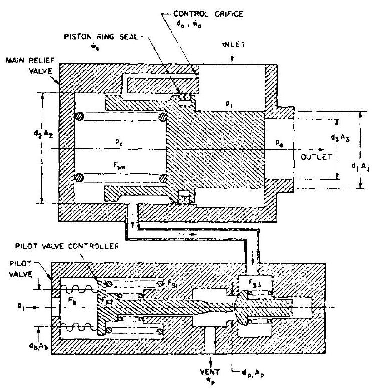 Figure 7-68.-Schematic of a typical high-capacity, pilot-operated tank gas pressure relief valve.
controller also senses the tank pressure . When the latter reaches or exceeds the preset level, the pilot valve is actuated to crack. This vents the main relief valve actuator control pressure and, in turn, permits opening of the main valve. Main valve poppet position is a function of the control pressure, which in turn is controlled by the position of the pilot valve poppet and by the tank pressure. This correlation can best be illustrated by the following sample calculation.
Sample Calculation (7-12)
The following design data are given for the A-4 stage propulsion system main oxidizer tank relief valve (schematically shown in fig. 7-68):
Tank pressurant temperature, (helium gas) Relief pressure set point, Required maximum flow capacity, Main valve flow coefficient, Estimated leakage past the main valve actuator piston seal, Control orifice diameter, in Flow coefficient for control orifice and pilot valve, Diameters and areas of various elements, in; in Control pressure, psia Ambient pressure (14.7 psia maximum) Determine: (a) Dimensions of the main relief valve and force balance equations for various conditions (b) Dimensions of pilot valve poppet and actuator, and force balance equations
Solution
(a) Main relief valve.-The valve is sized for an isentropic compressible flow through an orifice. From equation (7-24), the main relief valve port area
Since (from fig. 7-53)
Required minimum travel of the main valve to the fully opened position
Force balance equations of the main relief valve poppet at various conditions: (1) Basic equation:
(2) Condition at cracking:
(3) Condition at any intermediate valve position:
(4) Fully open condition:
(5) Condition at start to reseat:
(6) Fully reseated:
where
| main valve seating force, lb | |
|---|---|
| preload and rate of main | |
| valve spring, | |
| main valve poppet travel in- termediate and fully open | |
| position |
(b) Pilot valve.-The pilot valve flow capacity must be larger than the combined flow rate of control orifice and leakage past the main valve actuator piston seal for adequate venting of . From equation (7-24), the flow rate of the control orifice
The total flow into the control cavity, .
Setting the flow capacity of the pilot valve 50 percent higher, its flow crapacity results as
It is desirable that this flow be maintained freely at all points, independent of back ; sures. This is achieved by maintainirg sonic velocity, i.e., critical or supercritical pressure ratios, at the restrictions. Thus, the maximum allowable control pressure
Based on this pressure, and using equation (7-24), the required minimum pilot valve port area results as
Required travel of the pilot valve to the fully open position
Force balance equations of the pilot valve poppet and actuator: (1) Poppet:
(2) Actuator:
where
$F_{p} \quad=$ pilot valve poppet seating
    force, lb
$F_{\mathrm{a}} \quad=$ pilot valve actuating force, lb
$F_{b} \quad=$ sensor bellowe force, lb
$F_{s_{1}}, F_{s_{2}}, F_{s_{3}}=$ forces of the various springs
When $F_{\mathrm{a}}>F_{\text {p }}$, pilot valve starts to open.